ESA SP-348, p 357
OBJECTIVES OF RESIK SOLAR CONCAVE SOFT X-RAY SPECTROMETER FOR CORONAS-F MISSION
J.
Sylwester1 and R.D. Bentley2
1 Space Research Centre, Polish Academy of Sciences, Wroclaw
2 Mullard Space Science Laboratory, Holmbury St. Mary, Dorking, Surrey, U.K.
ABSTRACT
Several institutes are involved in construction of the high sensitivity soft X-ray spectrometer RESIK, to be flown aboard the Russian Coronas-F satellite in 1994/95. In the paper the scientific objectives of the instrument are discussed, arising as a compromise between the scientific interests and constrained by good quality large area crystals obtainable, detector dimensions and the geometry of Bragg concave crystal reflection. Four bands have been selected to perform measurements of the solar active region and flare spectra: 2.97-3.24
Å, 3.15-3.25 Å, 4.95-5.15 Å, and 6.50-7.19 Å. Special "Dopplerometer" arrangement of the crystals will allow to assign "absolute" wavelength scale and determine the role of directed and turbulent flows in the source. Interpretation of the line and continuum intensities will permit to derive the differential emission measure for plasma temperatures T > 3 MK, and to determine the composition (relative to H) of the coronal plasma for many elements including these with different first ionization
potential.
1. INTRODUCTION
Resik is a Bragg crystal spectrometer designed to observe solar active region and flare plasmas. A unique feature of its design is that channels with similar wavelength coverage are deployed with their dispersion axis opposed, thereby allowing the instrument to act as a Dopplerometer, and thus distinguish between offset and mooving sources. The RESIK instrument is to be constructed by a consortium including at the moment the Mullard Space Science Laboratory, the P.N. Lebedev Pysical Institute, Moscow (FIAN) and the Space Research Centre of Polish Academy of Sciences. RESIK has been selected for inclusion aboard the Koronas-F (FIAN coordinated satellite). This satellite is one of a serie of observatories devoted to solar physics that will be launched about at the time of the SOHO
operation.
2. THE CORONAS-F MISSION
The primary objective of the experiments aboard the CORONAS-F satellite is to study solar flares and active regions, global solar oscillations, elemental composition of solar plasma and solar irradiance variability. Besides RESIK the CORONAS-F will carry a number of instruments with complementary science objectives. An important one is DIOGENESS (Ref. 1) which will measure spectra with a flat crystal spectrometer in the wavelength range of the two short wavelength intervals of RESIK. DIOGENESS will have the capability to measure the distribution of the soft X-ray brightness of the source in bands 2-4-8 keV with angular resolution " 5 arcsec in the plane of dispersion, will locate the source offset relative to the satellite axis and will provide broadband whole-Sun photometry in the ranges 2-4-8 keV up to 100 times per second. The spectra from DIOGENESS would also be helpful in verifying in orbit the performance of the X-ray reflecting properties of the concave RESIK crystals.
The RES-K spectropolarimeter will measure high resolution spectra in the vicinity of selected strong X-ray lines. The TEREK complex (similar to that flown on the PHOBOS mission) will produce images of the Sun in soft X-rays and UV, and the white light coronograph images with
resolution of ~1 arcmin. There will also be instruments aboard the CORONAS-F satellite which will allow high resolution measurements of the gamma-ray flare spectra, the spectrometry of charged particles and neutrons, and the measurements of the solar UV and radio fluxes. The total mass of the scientific payload will be approximately 350 kg. The satellite is to be put in a circular orbit with an altitude of 500 km. The orbital plane will be inclined at 82° to the equator, resulting in periods of several days of uninterrupted observations of the Sun - the longest satellite night will last for 35 minutes. Passage through the radiation belts will require the X-ray detectors to be turned off for a maximum of 30% of the orbital period. The satellite will be re-pointed whenever its main axis drifts more than 10 arcmin away from the centre of solar disc. The guaranteed drift rate will be less than 3.6 arcsec/s (most probably much less) on each of the three gyro-stabilized axes. The operational lifetime of the satellite is expected to be not less than 2 years.
3. SCIENTIFIC OBJECTIVES
The primary objective of the RESIK spectrometer is to study the balance of the solar active region and flare energy, contained hi its main thermal reservoir. Studies of the energy balance are important for better understanding of the heating mechanisms and processes leading to the energy dissipation, transport and redistribution between its various forms. As has been extensively discussed in the literature, the important components of the active region and/or flare plasma energy are: the energy deposited in terms of heat , the energy radiated away, the energy conducted away, the energy which flows into and out of the regions due to moving plasma, the energy contained in the turbulent motions, and the energy contained in the accelerated particles. The energy terms related to the increase of the potential energy of the evaporated plasma, and the kinetic energy of the inflowing plasma, may be regarded as insignificant in comparison to the other ones. In order to estimate all the terms important for studies of the energy balance, high spectral resolution, which time resolution and high sensitivity are required for RESIK. The analysis of emission line profiles in the soft X-ray spectrum provides information on the magnitude of directed and turbulent motions present in the thermal plasma. The relative spectral line intensities are essentially related to the distribution of temperature within the source plasma, while the absolute line intensities are proportional to plasma emission measure. Spectra of initial flare phases observed by the Solar Maximum Mission (SMM), YOHKOH Bent Crystal Spectrometers and the Solflex instrument aboard the P78-1 satellite indicate that, for most of flares observed on the solar disc, a blue-shifted lines or line component of strong lines are present. The characteristic velocity of the plasma responsible for blue-shifted emission is around 100 - 600 km/s but may be larger for very energetic flares, and is commonly related to the average velocity of the material being evaporated from the dense transition region. The Bragg spectrometers on HINOTORI, SMM , YOHKOH and P78-1 have shown that in flares, as well as in the developing active regions, spectral lines are much wider than is expected from their thermal broadening. The motions seem to be random, since they appear unrelated with distances from the disc centre, but whether they are strictly "turbulent" is presently unclear. In order to clarify the nature of the line broadening, high sensitivity spectrometer observations would be of great value. The RESIK would have similar or higher sensitivity than the SMM-BCS for the Ca
XIX lines. With this instrument it would be possible to study the Ca
XIX and Ca
XX resonance line profiles (widths, blue-shifts etc.) earlier in time,
when, as observed by YOHKOH (Ref. 2), the relative intensity of the shifted to unshifted component is large or of the same order. A unique characteristic of RESIK is that the diffracting crystals are to be mounted in a so-called
Dopplerometer geometry to allow for unambiguous distinguishing between the Doppler and line shifts due to spatial displacements. Line shifts due to velocities of less than 5 km/s can possibly be detected for stronger flares. The absolute velocity scale will be calibrated in-flight by looking to the Doppler shifts due to the motion of the satellite relative to the Sun.
RESIK will permit a detailed study of the flare heating function using the diagnostic diagrams as proposed in (Ref. 7).
A high sensitivity instrument like RESIK could also ascertain whether or not transient ionization occurs in the plasma. Numerical simulations of this effect performed in (Ref. 3) have shown that an improvement in the sensitivity offers a chance to derive plasma densities below
1011 cm-3 threshold (from the analysis of line ratios sensitive to non-equilibrium effects).
One of the most intriguing results to emerge from the SMM BCS was the discovery (Ref. 4) that the abundance of calcium varies by a factor of up to 4 between flares and that there exist differences of the Ca abundance for flares occuring in different active regions (Ref. 5). The high sensitivity of RESIK and its broad spectral coverage will allow a study of the composition of flare and active region plasmas for a range of elements including S, Ca, Fe, Ar, Mg and Si. By measuring the line fluxes formed In a wide temperature interval it would be possible to perform a differential emission measure analysis.
It has been observed for the Mg
XII L line, that for components of the La doublet, the intensity ratio often departs
from the theoretically predicted value 1/2. It has been suggested (Ref. 6) that opacity effects may be responsible for the observed deviations. RESIK spectra would allow the study of such doublets for Ca
XX and S
XVI resonance lines. It would be interesting to study the relative intensities of the lines of higher members of the series, with excitation energies close to the ionization and thermal limit. The intensity of such lines might reflect the influence of populating processes like charge exchange, recombination etc. To fulfil such a broad scientific objective we have to combine possibility to observe flares and active regions at the period of low expected solar activity and take into account stringent construction limitations described below. We have selected Ca
XIX resonance line as primary for the line profile asd Doppler-shift flare studies (channels A and B in Table 2) and relativly wide bands (with no possibility of line profile analysis) for differential emission measure and abundance studies in flares and non-flaring active regions (channels A' and B').
line, that for components of the La doublet, the intensity ratio often departs
from the theoretically predicted value 1/2. It has been suggested (Ref. 6) that opacity effects may be responsible for the observed deviations. RESIK spectra would allow the study of such doublets for Ca
XX and S
XVI resonance lines. It would be interesting to study the relative intensities of the lines of higher members of the series, with excitation energies close to the ionization and thermal limit. The intensity of such lines might reflect the influence of populating processes like charge exchange, recombination etc. To fulfil such a broad scientific objective we have to combine possibility to observe flares and active regions at the period of low expected solar activity and take into account stringent construction limitations described below. We have selected Ca
XIX resonance line as primary for the line profile asd Doppler-shift flare studies (channels A and B in Table 2) and relativly wide bands (with no possibility of line profile analysis) for differential emission measure and abundance studies in flares and non-flaring active regions (channels A' and B').
4. DESIGN OF RESIK
The instrument consists of the three separate modules: BS - payload spectrometer block, BE - interface electronic block and PRAM -microcomputer block. BE and PRAM are located inside the pressurized section of the CORONAS spacecraft. The mass and power consumption of each block are given in
Tablel.
Table 1: Mass and power consumption for individual blocks.
| Block |
mass[kg] |
power [Watts] |
| spectrometer |
8.6 |
9 |
| electronics |
6 |
6 |
| PRAM |
4 |
4 |
4.1 .Design of the Payload Spectrometer Block
It was decided to design RESIK spectrometer block (BS) using crystals as the dispersive elements. BS will contain four concavely bent crystals (A, A', B, B' in Table 2) that cover wavelength ranges of diagnostic importance. In Table 2 the crystal parameters and the wavelength ranges covered are given. The four crystals are mounted in two sections. We have chosen to bend the crystals to a concave cylindrical profiles, since this geomery causes a sligth focussing effect and allows to reduce the overall size of the block. There are no moving parts and no collimator is used.
Table 2: Characteristics of RESIK channels.
| Chanel
Band (Å) |
A
2.97-3.24 |
A'
6.50-7.19 |
B
3.15-3.25 |
B'
4.95-5.15 |
| Crystal |
Ge |
EDDT |
Ge |
Si |
| 2d [Å] |
4.000 |
8.808 |
4.000 |
6.284 |
| Radius [cm] |
169 |
154 |
329 |
280 |
| Length [mm]2 |
184 |
193 |
141 |
147 |
| Width [mm] |
40 |
40 |
40 |
40 |
| Sensitivityb |
1 |
0.4 |
2 |
18 |
| |
|
Important lines and
characteristic temperature of formatic |
| Ion |
Ca XX
La |
Si XIII |
Ca XIX |
S XV |
 [Å]
[Å] |
3.02 |
6.65 |
3.18 |
5.04 |
| T [Mk] |
56 |
10 |
32 |
16 |
| Ion |
Ca XIX |
MgXII |
|
|
|
[Å] |
3.18 |
6.65 |
|
|
| T [Mk] |
32 |
10 |
|
|
a - without mounting needs
b - with respect to the SMM-FCS, scanning at 100 arcsec/s. Other sensitivities are with respect to the SMM-BCS Channel f 1
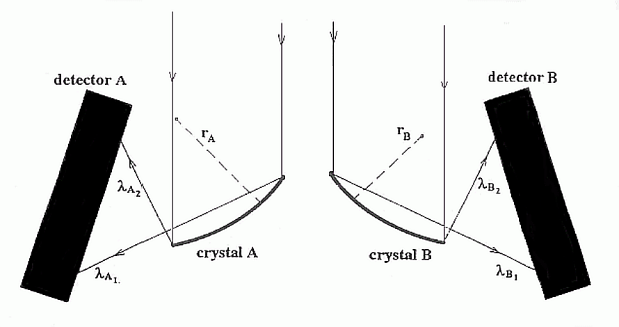
Possible confusion due to overlapping the spectra from multiple flares or active regions is possible to overcome using the data from DIOGENESS slit collimator. The sizes of the crystals are larger than used by SMM BCS and comparable to these used in YOHKOH BCS. In Fig. 1. we show an example of the ray paths in
BS of RESIK.
The incoming radiation strikes the crystals where it is diffracted into detectors located inside each structure.
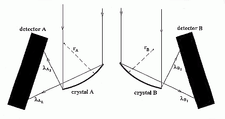
Fig. 1: Scheme of the ray paths in the Dopplerometer. The incoming X-ray radiation is "reflected" by a concave cylindrical crystal surface bent to the radius r. Diffracted radiation is detected in one of the two sections of the position sensitive detector.
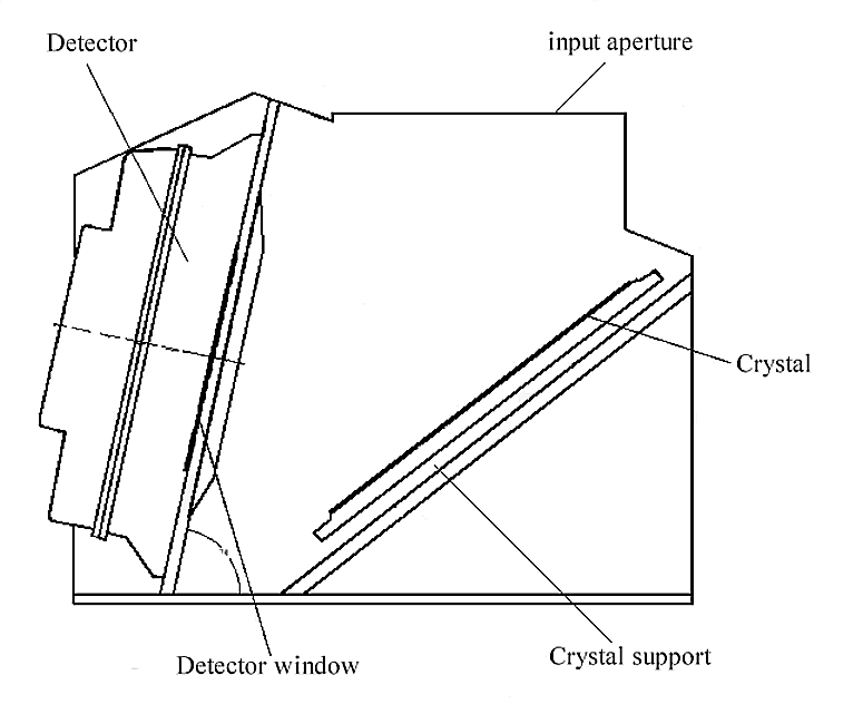
A drawing of one of the sections is shown in Fig. 2. The dimensions of the crystal-detector assembly have been optimized to allow for alignment and calibration to be made at the vaccum stand at the Rutherford-Appleton Laboratory - the same stand which has been used to calibrate the
YOHKOH BCS.
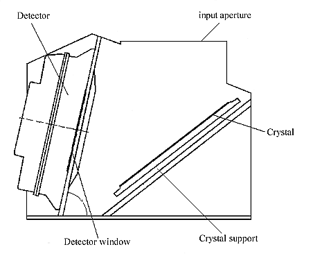
Fig. 2: Schematic view of the mechanical assembly of one of the sections of the spectrometer block
(BS).
Within the spectrometers an optical technique is used to set each crystal at the appropriate Bragg angle with the precision better than ~15 arcsec. Each section has three feet to enable accurate mounting on the common base. Each contain two crystals which have been paired so as to have approximately the same Bragg angles. Similar Bragg angles are necessary because of the nature of the detector used. The detector combines two windows (each measuring radiation from individual crystal) into one unit. The angle of incidence of the "reflected" ray onto detector should be as close to normal as possible for both windows. This condition imposes a stringent limitations on the possibility of choosing the wavelength ranges for both crystals. The other limiting factor comes from our choice of the Dopplerometer configuration of the two sections. This requires the coalignment of the dispersion planes for all crystals, while the direction of the dispersion should be opposite for sections measuring ihe same strong spectra! line ( for instance Ca
XIX resonance line for channels A and B). To illustrate what is the sensitivity of the instrument, we show in Table 3 expected count rales at the maxima of the strongest lines calculated for a typical emission measure for several plasma temperatures (T = 5 MK represents hot active region, the other temperatures correspond to flare conditions). Ecpected background count rates are of the order of 0.01 count/s.
Table 3: RESIK expected count rates in selected lines for emission measure 1048
cm-3 for selected temperatures.
| |
T [MK] |
|
Line
|
L [Å] |
5 |
10 |
15 |
20 |
| Ca XX |
3.0185 |
- |
0.06 |
0.3 |
1.8 |
| Ca XIX |
3.1781 |
0.2 |
1.4 |
4.6 |
20.8 |
| S XV |
5.04 |
11 |
161 |
256 |
207 |
| Si XIII |
6.65 |
14.5 |
67.0 |
42.7 |
20.1 |
| Al XIII |
7.17 |
0.1 |
3.4 |
3.9 |
3.1 |
In calculating the response we have used the approach similar to that presented in (Ref. 8).
The wavelength resolution is set by the geometry of the spectrometers, the
crystal rocking curves and the X-ray position resolution of the detectors.
For channels A & B the width of thermal line profiles are much larger
than the width of the instrumental profiles. For A' & B' channels the line
shape is determined by the instrumental profile.
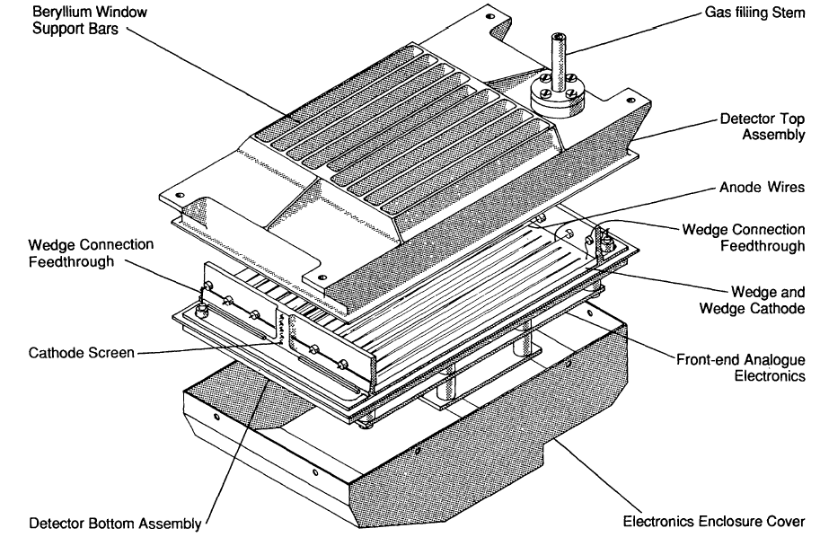
Detector construction and operation is similar to that adopted in the
YOHKOH BCS (Ref. 8). A wiev of the detector (from Ref. 8) is shown in
Fig. 3.
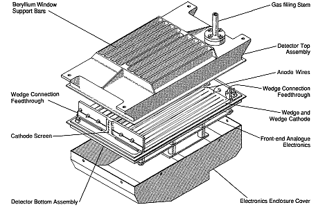
Fig. 3: A view of the double proportional counter. A single one-dimentional position readout pattern is common to both
halves. Each half detector registers X-rays from a single crystal and has two connected anode
wires. The halves are electrically separated by a screen of cathode wires. The top and bottom assamblies are sealed together by electron beem
welding.
4.2 Analogue and Digital Electronics
The double-wedge position readout pattern of the detector and the front
electronic is similar to that designed for YOHKOH BCS and is described and
illustrated in (Ref. 8). The mam function of the electronic block is to
interface the amplified analogue signals coming from payload BS block to the
digital format acceptable by PRAM on board computer. The PRAM receives the data from the interface electronics at the rate in excess of 10
kbits/s and process and transfer them to the on-board memory at the similar rate. Capacity of the allocated on-board memory is 15 Mbits. This is enaugh to register
~3 104 spectra. The on-board memory is dumped to Earth once per day, i.e. the average rate of gathering the spectra would be about one spectum per 3 s or a complete set of four spectra in ~10 s. The internal SRAM memory (~2 M bis) of the PRAM computer can be used as a queue memory and store about
103 spectra with the time resolution up to ten times per second if the count rate statistics is high enough. A special dual radio link will allow PRAM to be directed or reprogrammed from the ground during radio visibility sessions (at least twice a day).
5. INSTRUMENT CALIBRATION
The spectrometer block BS is expected to be calibrated at the Rutherford-Appleton Laboratory using the same calibration procedure which was used to align and calibrate the YOHKOH BCS. Description of the procedure and the calibration unit can be found in (Ref. 8).
6. SUMMARY
A short description is given of the scientific goals and the construction of the concave Bragg crystal spectrometer (RESIK) to be placed aboard the CORONAS-F solar observatory. The scientific objectives of the instrument are complementary to that of the SOHO instruments. Common analysis of SOHO , RESIK, DIOGENESS and other instruments aboard CORONAS spacecraft will allow to study for instance the differential emission measure distribution in flares up to 50 MK, and to look for possible dependence of abundance anomalies on the temperature. The RESIK data by itself will allow to study the energy balance of the main thermal energy reservoir for avctive regions and flares.
Acknowledgements
The construction of RESIK is covered by the grant No 2 2150 92 03p/24 from the Polish Comeettee of Scientific Research and SERC GR-G 10517 from the Science Engeneering Research Council, UK.
REFERENCES
1. Sylwester J & Farnik F 1989, Bull. Astron. Inst. Czechosl., 41, 3, 149 -157.
2. Culhane J L & al 1993, Advances in Space Research, submitted
3. Mewe R & al 1985, A & A, 152, 299 - 236
4. Sylwester J & al 1984, Nature, 310, 665 - 666
5. Sylwester J & al 1993, to be published
6. Sylwester B & al 1986, Solar Phys., 103, 67-87
7. Jakimiec J & al 1992, A & A, 253, 269 - 276
8. Culhane J.L. & al 1992, Solar Physics, 136, 89 - 104
BACK