| No. | Date | UT | Ha | GOES | Location | NOAA | Imax/I0 | Correl. |
| 1 | 24 Oct. 1991 | 22:40 | 1N | M9.8 | S12 E46 | 6891 | 1.06 | GOES |
| 2 | 15 Nov. 1991 | 22:38 | 3B | X1.5 | S13 W19 | 6919 | 1.35 | L |
| 3 | 03 Dec. 1991 | 16:38 | 2B | X2.2 | N17 E72 | 6952 | 1.05 | M1 |
| 4 | 26 Jan. 1992 | 15:31 | 3B | X1.0 | S16 W66 | 7012 | 1.10 | L |
| 5 | 24 Apr. 1992 | 19:19 | 2B | M1.2 | N13 W00 | 7138 | 1.05 | L |
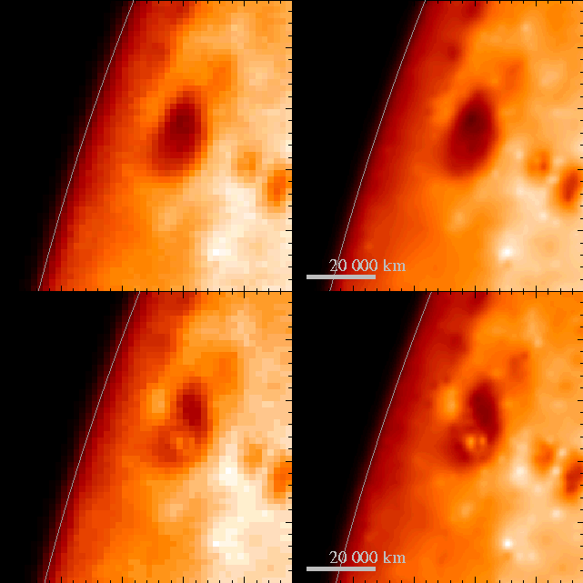
Figure 1: The original (left panel) and deconvolved (right) optical images (NaBan filter) for the flare on 3 December 1991. In the upper row initial flaring image taken at 16:33:37 UT (the first available) is shown while in the lower row the image taken at the WL flare maximum (16:36:39 UT) is displayed.
The data set used in the present analysis consists of flare sequences of the Soft X-ray Telescope (SXT) and aspect sensor images taken in full resolution. These images (64×64 pixels) have been deconvolved using ANDRIL algorithm (Sylwester and Sylwester, 1998). The deconvolution removed the image blurring due to the instrument point spread function and increased numerically the spatial resolution in the images down to 1 arc sec. As a result of deconvolution we obtained corresponding sequences of images (320×320 sub-pixels; with 5×5 sub-sampling). It is known, that oversampling (super-resolution techniques) do introduce additional uncertainty towards the restored intensity images due to ill-conditioned nature of the problem. This has been studied in details for case of ANDRIL SXT image deconvolution algorithm by Sylwester and Sylwester, (1999). Using the results of this study it is possible to assign uncertainty to each of intensity values as obtained in the process of deconvolution. A typical uncertainty increase has been found to be around a factor 4 �5. In areas of high signal-to-noise values (white light images, maxima of X-ray emission) this increase of uncertainty does not noticeably influence the results of the present study.
The deconvolved images have been carefully co-aligned to within the fraction of arc sec as discussed further-on.
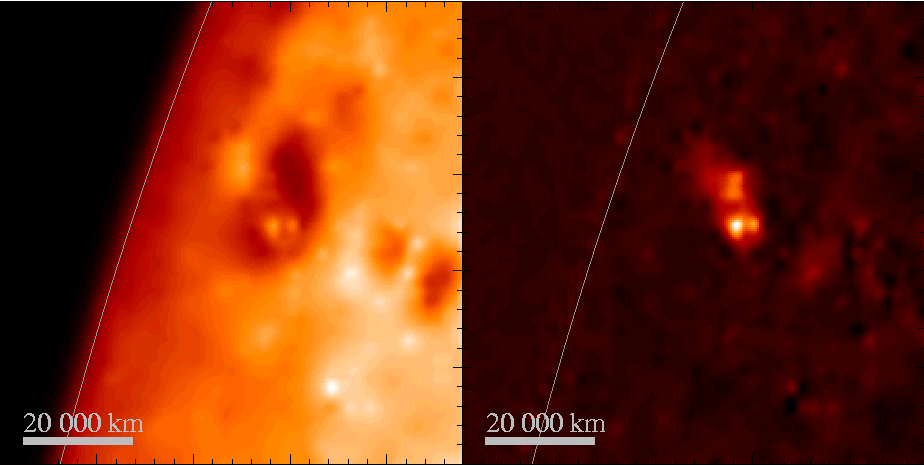
Figure 2: The WL deconvolved (left) and fixed differences (relative to initial frame) image for the maximum phase (16:36:39 UT) of 3 December 1991 flare. See text for details.
This perfect co-alignment we have achieved by using dedicated image correlation algorithm based on the idea of additional pointing corrections discussed by Siarkowski et al. (1996). In case of deconvolved optical images we
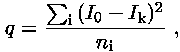
allowed for the additional (fractions of sub-pixel) alignment shifts in order to reach the best image correlation between reference (initial) and analysed frames. The negatives of WL images have been used in cross-correlation. By doing this we avoid problems due to the white-light contribution of the flare itself. As the parameter being optimized in the correlations, we have used the following ''surface distance'' characteristic q:
| (1) |
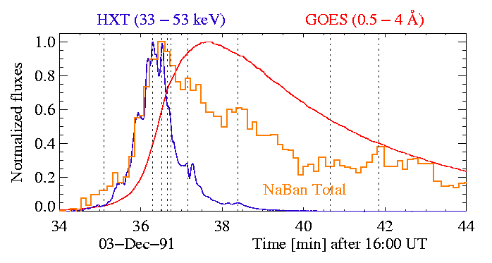
Figure 3: The hard X-ray (M2 HXT; blue), optical (NaBan; orange) and soft X-ray (GOES 0.5-4 Å; red) fluxes for 3 December 1991 flare. The dashed vertical lines indicate nine times at which the contours are presented in the next Figure.
Fast, systematic changes of the morphology of WL emission can be recognized. During the early flare phase the northern patch dominates. Around flare maximum two patches coexist with the southern one becoming more intense and structured (double, as shown in Figure 2). The relative importance of northern and southern patches is similar during the early decay. Later on an additional compact, well separated region develops in the south-western part of the investigated area. Although it does not dominate the total WL flare emission, it is significant for about 4 min during late decay phase. On the right bottom frame in Figure 4 we have indicated three selected areas called a, b and c. In the upper panel of Figure 5 the time variations of NaBan fluxes integrated within the selected sub-areas are presented. In order to allow for better visualization, the base levels of the vertical scale for curves a and b are displaced vertically as indicated by dashed horizontal lines at the onset of each plot. In the lower panel of Figure 5 the hard X-ray light-curves are presented. In this case individual light-curves have also been shifted vertically. It is seen that the emission in all sub-areas chosen rise nearly simultaneously with the emission in M2 HXT channel. The onset of WL emission is slightly delayed for region c. The rise time profile for all three regions is nearly the same and amounts to ~ 1 min. The most dynamic and intense in WL is the emission in the area a. The full width at half maximum (FWHM) of NaBan light curve for this area is ~ 2 min only. The emission in the faintest area (c) has similar behaviour in this respect.
Figure 4: The sequence of optical (NaBan filter) deconvolved fixed differences image contours for 3 December 1991 flare. Contours are plotted at levels 0.5, 0.7 and 0.9 of the maximum for individual frames. The frames presented correspond to times indicated in Figure 3. Thick red line connects the centres of gravity for the main patches and its length indicates the distance. Note the change of inclination of this interconnecting line. The dashed lines on the last image divide the 100×100 sub-pixels area into three sub-regions (a, b and c).
However for area b, the FWHM of WL curve amounts to ~ 4 min. This region persists for much longer time in comparison with regions in areas a and c. It decays much slower following rather the soft X-ray (GOES light curve) with a kind of plateau seen after the maximum.
In this context it seems interesting to investigate the possible correlations of the emissions variability in various energy bands for individual areas.
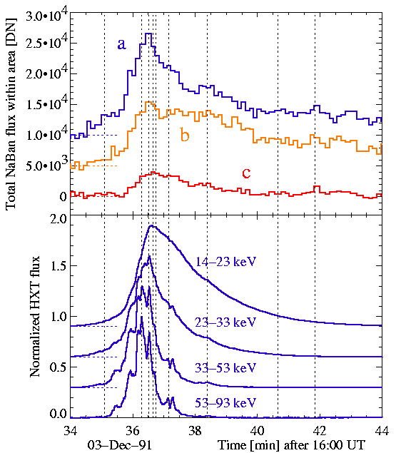
Figure 5: The upper panel shows the optical light curves (NaBan filter) for three areas (a, b, c) of 3 December 1991 flare. The location of the areas is indicated in Figure 4. In the lower panel the flare-integrated hard X-ray light-curves are shown for all channels of HXT. The curves are vertically displaced for the sake of better visualization. Corresponding base levels are indicated as dashed horizontal lines at the onset of each plot.
In Figure 6 we present correlation diagrams in which the dependence between the WL emission (NaBan filter), soft X-ray radiation (GOES 0.5-4 Å) and hard X-ray radiation (all HXT channels) are displayed for regions a, b and c separately. The plots have been normalized. The colour (shades) of data points and the connecting lines are time dependent as indicated by colour bar at the top of the Figure. Darker points represent earlier times. Generally it is difficult to find one-to-one correlation between WL and specific X-ray radiation during entire investigated period. The best correlation is observed between the WL and M1 HXT channel (23-33 keV) emissions for the area a.
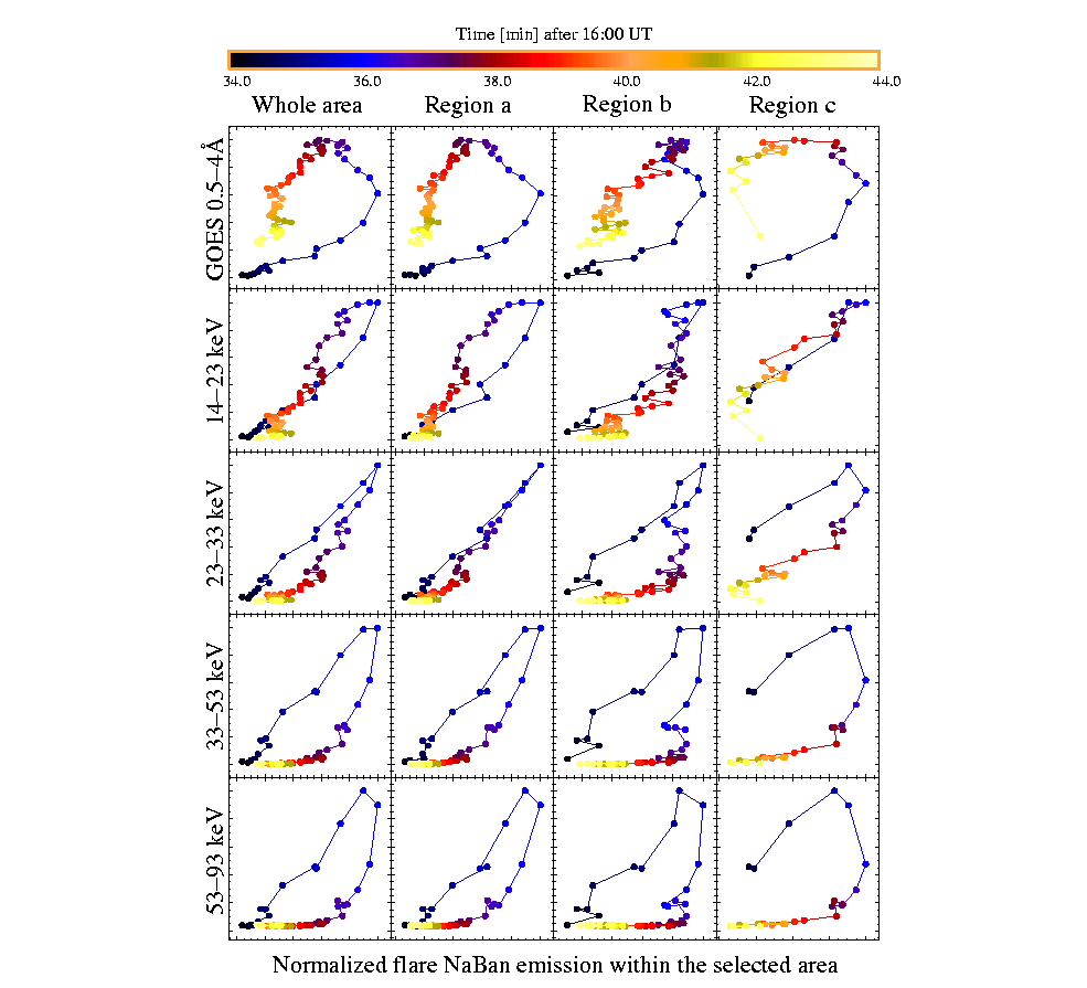
Figure 6: The diagrams of the WL (NaBan filter) vs X-ray radiation for the entire flare FOV and for individual selected regions (a, b, c) of 3 December 1991 flare. The X-ray flux represents the total flare emission in each case. See the text for details.
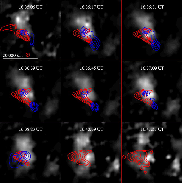
Figure 7: The sequence of WL (NaBan; grey scale), SXT (Al12; red contours) and HXT (M2; blue contours) are superposed for 3 December 1991 flare. For the last two frame the M2 signal was too weak to allow for HXT image reconstruction. See text for details.
In order to better understand the observed relation of the WL and X-ray emissions of the flare, we attempted to compare the spatial location of the sources contributing to investigated emission bands.
In Figure 7 the sequence of nine images for times indicated by vertical dashed lines in Figure 3 are presented. The 49×49 arc sec field of view containing the main flaring structures has been selected. In the background, the NaBan fixed positive differences image is displayed in the grey scale. The dashed line contours over-plotted represent the emission in the SXT Al12 deconvolved images while the MEM reconstructed hard X-ray images (M2 HXT channel) are shown as superimposed solid line contours. The contours are drawn at the levels: 0.3, 0.5, 0.7 and 0.9 of respective maximum values for individual frames. The frames selected cover the entire WL flare phase and represent characteristic times of flare evolution, mostly when individual spikes are observed on the hard X-ray light-curve (see Figure 3). It is evident from the images presented in Figure 7 that the morphology of WL and X-ray emission is different and changing fast during the evolution. The most dynamic changes take place during the rise and decay phases while during the maximum phase the morphology of X-ray radiation does not change substantially. The soft X-ray emission is rather elongated at the onset of the impulsive phase and becomes crescent-shaped later on. The hard X-ray emission (M2 HXT) is rather compact at the beginning and is concentrated in two small patches located ~ 9000 km South to the brightest optical emission. At this phase the WL emission centres are not at all co-spatial with the X-rays. One of M2 patches is elongated in N-S direction and the second, more intense is round in shape. Later on during the flare WL maximum phase, both patches are round and well separated. During the WL decay the northern patch ceases the first.
It is clearly seen that the optical, soft and hard X-rays are not co-spatial (according to our best co-alignment). Only the northern patch seen at 16:36:17 UT frame appears to be co-spatial for all emissions displayed (optical, Al12 SXT and M2 HXT). However this represents the one and only perfect co-alignment case and therefore could be regarded as a coincidence (result of projection effect).
From inspection of Figure 7 it is also seen that substantial changes took place in the morphology of various emissions during the investigated period (few minutes of initial flare evolution). The WL emission is concentrated North to the X-ray emission in the initial frame while in the last frame presented, the WL emission is concentrated in the central part of the frame apart the maxima of soft and hard X-ray emission patches.
In order to better compare the location of emission in various energy bands we present in Figure 8 the MEM reconstructed HXT images for all four channels at the time of hard X-ray flare maximum (16:36:39 UT) together with Al12 and WL emission contours superimposed. It is seen that at this particular time the best spatial overlapping between the WL and X-ray sources is observed for lower energy HXT channels (L and the M1) while the largest displacement is observed for the highest energy range (53-93 keV; H channel). The strongest patch of M1 channel emission is almost co-spatial with that observed in soft and optical bands. For the HXT H channel the maxima of optical and hard X-ray emissions are separated by ~ 9000 km in projection.
Based on inspection of Figures 4 and 7 it is evident that during almost all investigated period two patches of emission can be distinguished both in the WL and in hard X-ray range.
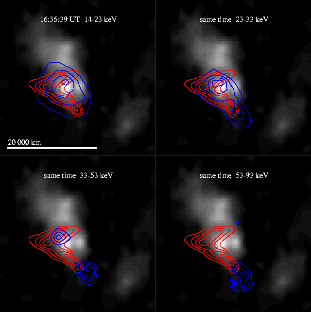
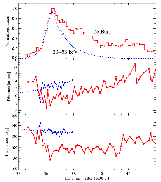
Figure 9: The time variations of the distance (the middle panel) and inclination (bottom panel) between two main patches observed on NaBan deconvolved images red and M2 blue images (dotted line) for the flare on 3 December 1991. The top panel shows corresponding NaBan and M2 HXT normalized light curves for the comparison.
The hard X-ray patches are more separated except for the very beginning of the rise phase. In the bottom panel of Figure 9 we present the time variations of inclination of the line connecting the two patches. After the initial drop of this angle (flare rise) inclination does not change substantially fluctuating around the average value of about 95� for about 5 min. Later on this inclination assumes another average value ( ~ 115�) for the last 2 min of observations. The average inclination of the line connecting the hard X-ray patches corresponds to different value ~ 135� after the initial excursion.
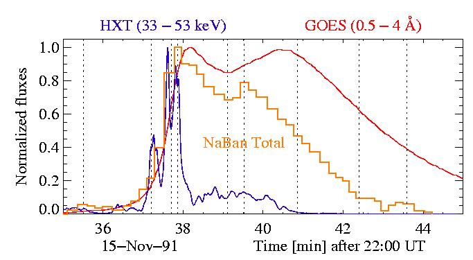
Figure 10: The hard X-ray (M2 HXT channel; blue), optical (NaBan; orange) and soft X-ray (GOES 0.5-4 Å; red) light curves for 15 November 1991 flare. The dashed vertical lines indicate the times at which the images in Figure 11 are presented.
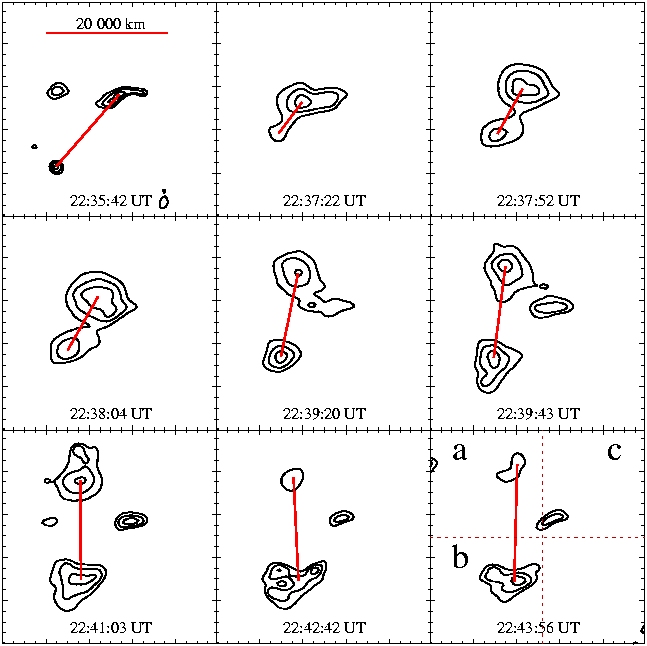
Figure 11: The sequence of WL (NaBan) deconvolved fixed differences images of 15 November 1991 flare made at selected times during the flare (as indicated by the vertical lines in Figure 10). The contours are drawn at the levels 0.5, 0.7 and 0.9 of respective maximum values. The dashed lines on the last image divide the 100×100 sub-pixels area into three sub-areas ( a, b, c ) containing the patches being analysed. The red line connects the emission centres of the characteristic patches and its length defines the distance between them.
The WL emission coming from the southern area (b) is of nearly the same intensity for the first and second component.
The correlation diagrams between the WL and the other types of integrated flare emission are presented in Figure 13. Again the colour (shade) of data points is related with the time elapsed from the start of the event. The darkest points represent the initial phase. In case of the 15 November 1991 flare, the best correlation can be observed between the optical and HXT L channel (14-23 keV) emissions except for sub-area c.
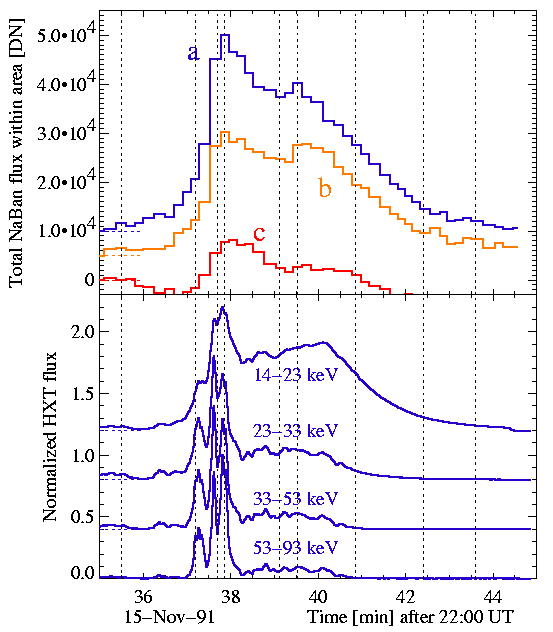
Figure 12: The upper panel shows the WL light curves (NaBan filter) for three sub-areas ( a, b, c ) of 15 November 1991 flare (as indicated in Figure 11). The lower panel shows the light curves of integrated hard X-ray flux as measured in all channels of HXT. The curves are vertically displaced for the sake of better visualization. Corresponding zero levels are indicated as dashed horizontal lines at the onset of each plot.
The relative locations of WL, soft and hard X-ray emissions (grey scale, dashed and solid contours respectively) during 15 November 1991 flare are presented in Figure 14 for selected times. The size of individual frame is (49×49 arc sec). On the last two frames (the late decay phase) the hard X-ray emission is too faint for the image to be reconstructed. The location of NaBan, Al12 and HXT M2 emission centres do not coincide during the flare. The closest are Al12 and M2 emissions in the second frame (22:37:12 UT) corresponding to the first hard X-ray spike on the light curve.
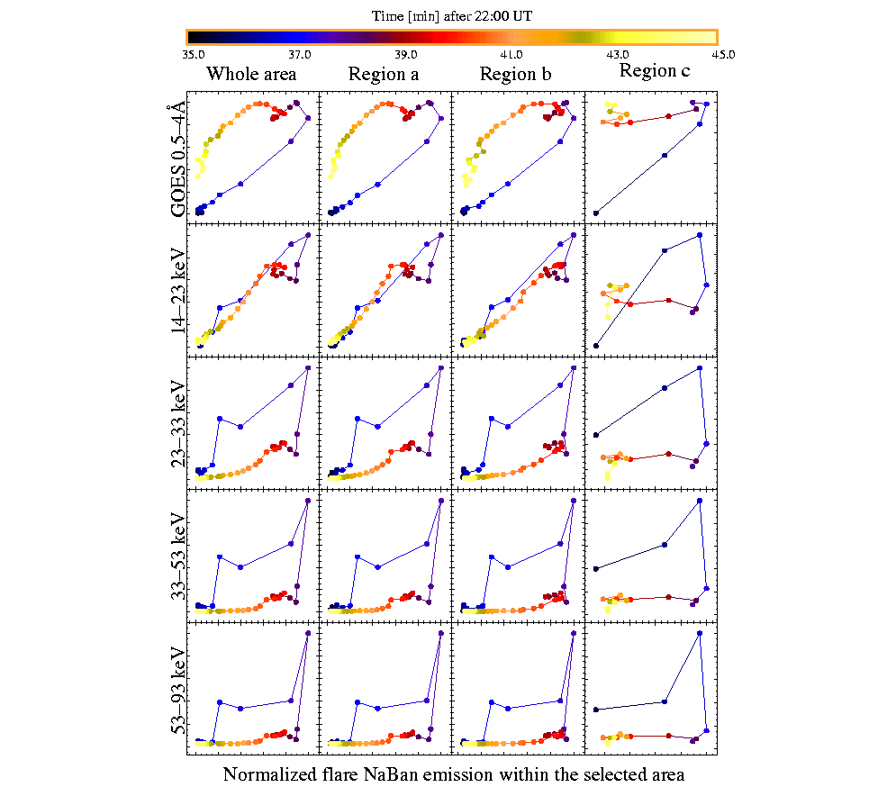
Figure 13: The diagrams of the WL (NaBan filter) vs X-ray radiation for three sub-areas ( a, b, c ) of 15 November 1991 flare.
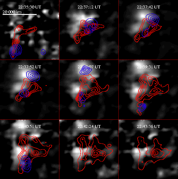
Figure 14: The sequence of (NaBan; grey), (Al12 SXT; red) and (M2 HXT; blue) superposed images for nine selected times (cf. Figure 10) of 15 November 1991 flare.
However this overlapping does not hold for the other times. The WL emission is displaced in comparison with X-rays for all frames analysed. This can be best seen on sequences of animated images available at www.cbk.pan.wroc.pl/publications/1999/White_light.htm for this and the other flares from Table I.
We welcome the reader to visit this web place. There are also available the colour versions of all the Figures from the present study.
The overall relative location of WL, soft and hard X-ray emissions for the time of flare maximum (22:37:52 UT) is shown in Figure 15. At this time the location of maximum HXT L channel emission (14-23 keV) is nearly co-spatial (to within 2 arc sec in projection) with the soft X-ray emission maximum (Al12).
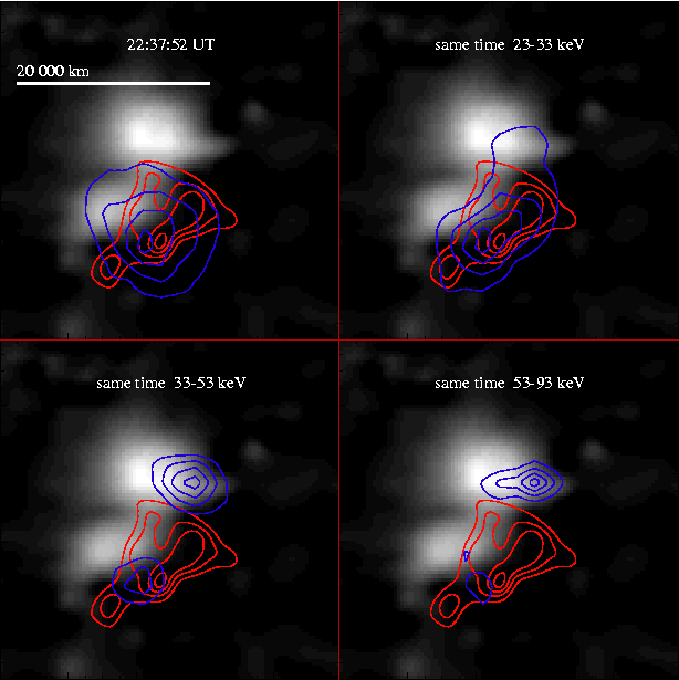
Figure 15: The NaBan fixed differences positive image for the flare of 15 November 1991 at 22:37:52 UT (in background, grey scale) superposed with the contours of MEM reconstructed HXT images for the four channels of HXT (blue lines) and SXT Al12 (red lines) deconvolved images at the closest available times. The contours are drawn at 0.3, 0.5, 0.7 and 0.9 of respective maximum values.
In the higher energy bands of HXT (M2 and H channels) the two characteristic emission patches are seen both in WL emission and X-rays. They are not at the same location however. The respective emission centres for WL and HXT are displaced by ~ 6000 km. We believe that the relative coalignment we have made is to within 1 arc sec when images of the same band are considered. We also believe that the observed displacements between hard X-ray and WL emission are real since it is not easy to bring the overall picture into perfect match by applying a simple shift of the boresight for individual spectral bands. Even by forcing perfect match for a particular time and spectral band, we fail to observe this match to be preserved for the other times during flare evolution.
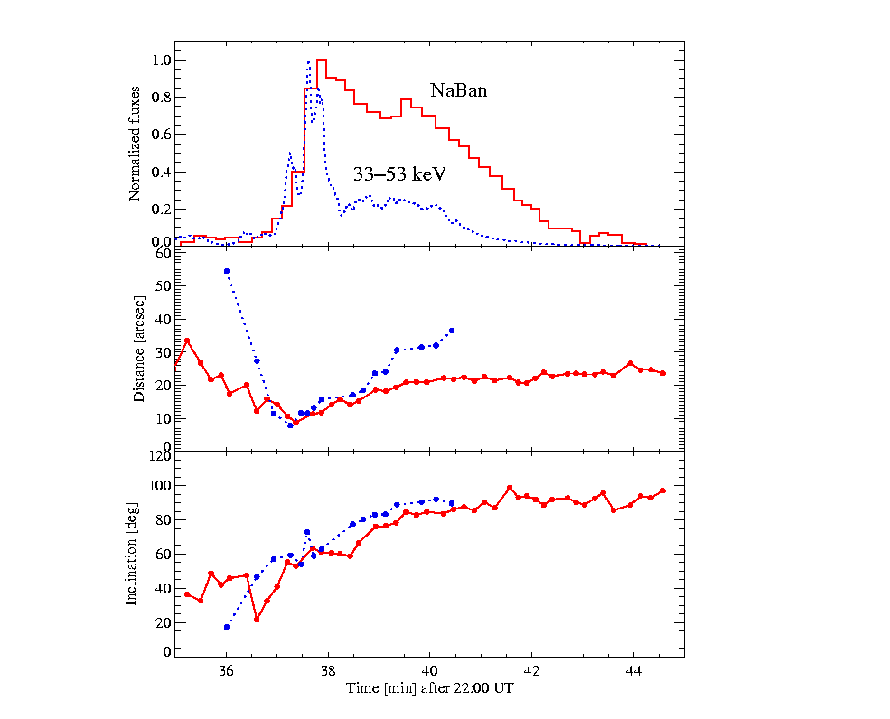
Figure 16: The time variations of the distance (middle panel) and inclination (bottom panel) of the line joining the two main emission patches (in a and b areas) as observed on (NaBan; red) deconvolved images (solid line) and (M2 HXT; blue) images (dotted line) for the flare on 15 November 1991. The top panel shows NaBan and M2 HXT normalized light curves for the comparison.
This is evident from Figures 9 and 16 where the separations and inclinations in WL and HXT images do not match.
The observed two main emission patches in areas a and b change their relative position during the flare evolution. This changes are illustrated in Figure 16. In the middle panel we have plotted the time variations of the distance between the patches (dashed line for the HXT M2 channel and solid line for the white light emission). In the bottom panel we present the time variations of inclination of the line connecting both patches. Similar trend of changes for the separation and inclination can be seen for both WL and HXT emissions. The strongest variability is observed during the impulsive phase. Initially the separation of the patches decreases (phase before the maximum of the impulsive phase) and increases again systematically afterwards. At the flare maximum phase the separation between WL and HXT patches is about the same, however the patches do not coincide spatially. The inclination tends to change (increase) from the very beginning of the event. The systematic lag exists between the inclination as observed in WL relative to the HXT. The WL inclination appears to lag behind respective HXT inclination by ~ 30 s.
The results of present analysis indicate that:
For the other flares not discussed in detail in this contribution, we also found the above conclusions applicable. In particular, the best correlation exists between time variations of WL (NaBan) emission and the 14-23 keV flux. For the flare on 24 October 1991, the WL emission correlates best with the GOES 0.5-4 Å flux. In the last column of Table I we indicate the X-ray band for which the best correlation has been observed with the WL emission.
We failed to accommodate observed properties of the investigated WL flares with present scenarios for the WL emission excitation mechanisms (i.e. particle precipitation, soft X-ray illumination).
It appears that the WL, SXT and HXT emissions are somewhat related, however indirectly. A higher level process(es) are envisaged to influence (in somewhat different way) activation of energy release in each of energy bands considered.
Ding, M.D., Fang, C., and Yun, H.S.:
1999,
Astrophys. J. 512, 454.
Fang, C., Yin, S.Y., Hiei, E., Ding, M.D., and Fu, Q.J.:
1995,
Solar Phys. 158, 387.
Hudson, H.S., Acton. L.W., Hirayama. T., and Uchida, Y.:
1992,
Publ. Astron. Soc. Japan NRO Report, 44, L77.
Hudson, H.S., van Driel-Gesztelyi. L., and Kosugi, T.:
1994, in
Proc. Kofu Symposium, eds S. Enome and T. Hirayama, NRO Report, 360, 397.
Lee, S.W., Yun, H.S., Hu, J., Fang, C., and Wang, J.L.:
1996,
Solar Phys. 163, 361.
Matthews, S.A., Brown, J.C., and van Driel-Gesztelyi, L.:
1996, in
Proc. Yohkoh Conference, eds R.D. Bentley and J.T. Mariska, PASP, 111, 304.
Matthews, S.A., Brown, J.C., and van Driel-Gesztelyi, L.:
1998,
Astron. Astrophys. 340, 277.
Rieger, E., Neidig, D.F., Engfer, D.W., and Strelow, D.:
1996,
Solar Phys. 167, 307.
Siarkowski, M., Sylwester, J., Jakimiec, J., and Tomczak, M.:
1996,
Acta Astron. 46, 15.
Sylwester, J., and Sylwester, B.:
1998,
Acta Astron. 48, 519.
Sylwester, J., and Sylwester, B.:
1999,
Acta Astron. 49, 189.