(Week 49, 2002, 02 Dec. - 08 Dec.)
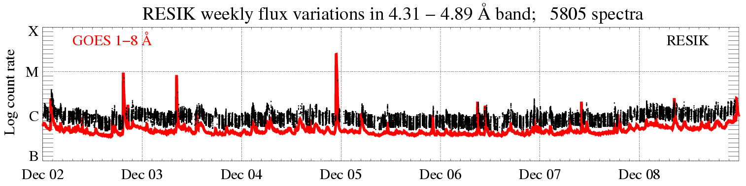
In the display above (click to enlarge), the solar X-ray fluence seen by RESIK (black points) is plotted atop GOES red line. Only periods with good spectral measurements are indicated. The total number of good spectral measurements is given in the title line.
| New mode: | '3rd
order reflections' (ORD3) is used as stand-by mode. For description see below |
| Calibrations made: |
No calibrations made |
| ADS Settings: |
|
|
|
|
| (ORD1) HV: Det. A - 1450 V, Det. B - 1389 V. | (ORD3) HV: Det. A - 1398 V, Det. B - 1325 V. | ||||||
|
Channel |
l Band |
ADS |
Channel |
l Band |
ADS |
||
| #1 | #2 | 3.37 - 3.88 Å | 35 - 85 | #1 | #2 | 1.16 - 1.29 Å | 110 - 230 |
| #2 | #0 | 3.82 - 4.33 Å | 70 - 120 | #2 | #0 | 1.27 - 1.44 Å | 110 - 230 |
| #3 | #3 | 4.31 - 4.89 Å | 55 - 110 | #3 | #3 | 1.44 - 1.63 Å | 110 - 230 |
| #4 | #1 | 4.96 - 6.09 Å | 90 - 160 | #4 | #1 | 1.65 - 2.03 Å | 140 - 230 |
|
software indexes |
|
software indexes |
|||||
|
spectroscopic notation (papers) |
spectroscopic notation (papers) |
||||||
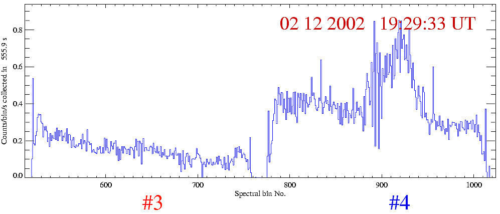
The third order spectra averaged over approximately 10 min.
interval during the maximum and decay phases of C9.5 flare observed on 2nd
December 2002 ~ 19:30 UT. Only the spectra obtained in #3 and #4 are displayed,
since for the other two channels the signal is at the noise level. The
approximate wavelength ranges observed are given in the Table ORD3 (above).
Clearly seen are spectral features corresponding to the transitions in Fe XXV-XX
ions (around 1.85 -1.88 Å).
Data gaps due to missing telemetry: ~ 65 minuts.
RESIK Third Order (ORD3) Reflection Spectra
One of the interesting possibilities is to use RESIK in order to observe spectra in higher orders of reflection. For the crystal cuts used, the second order reflections are prohibited for Si 111 crystals, while the third order reflection are allowed for both Si and Quartz crystals. Therefore, we selected to observe flare spectra in third order reflections. This selection is also more favourable in terms of available ADS and HV settings combinations. For the higher order reflections, as a direct consequence of the Bragg's law, it follows, that the wavelength of the 'reflected' radiation is inversely proportional to the reflection order "k", for a given incidence angle (q ).
k·l = 2d sinq
In order to
pick-up photons corresponding to higher-order reflection, it is necessary to adjust
instrument's settings accordingly. In the Table ORD3, we present the new settings adopted for 3rd order
reflection. The selection has been made based on the results of analysis of the in-flight ADS calibrations (Marek Siarkowski and Mirek
Kowalinski). These results will be described in more details in one of the forthcoming Weekly
Reports. By setting HV and ADS as indicated, we get rid of most of the contributions from the first
and/or second order reflection spectral contributions.
In the wavelngth ranges covered in third order reflection, one may expect to see
"hot" emission lines corresopnding to transitions in H- and He- like ions of Fe and possibly Ni. The strongest of them
are:
Table II
Lines expected to be present in the 3rd order spectra
| Ion | l (Å) | Transition | Key |
| Ni XXVII | 1.3501 | 1s2 1S0 - 1s 3p 1P1 | |
| Ni XXVII | 1.3517 | 1s2 1S0 - 1s 3p 3P1 | |
| Fe XXVI | 1.5024 | 1s 2S1/2 - 3p 2P3/2 | Lyb |
| Fe XXVI | 1.5035 | 1s 2S1/2 - 3p 2P1/2 | Lyb |
| Ni XXVIII | 1.5303 | 1s 2S1/2 - 2p 2P3/2 | Lya |
| Ni XXVIII | 1.5358 | 1s 2S1/2 - 2p 2P1/2 | Lya |
| Fe XXV | 1.5732 | 1s2 1S0 - 1s 3p 1P1 | |
| Fe XXV | 1.5750 | 1s2 1S0 - 1s 3p 3P1 | |
| Ni XXVII | 1.5885 | 1s2 1S0 - 1s 2p 1P1 | w |
| Ni XXVII | 1.5923 | 1s2 1S0 - 1s 2p 3P2 | x |
| Ni XXVII | 1.5966 | 1s2 1S0 - 1s 2p 3P1 | y |
| Ni XXVII | 1.6036 | 1s2 1S0 - 1s 2s 3S1 | z |
| Fe | 1.744 | Kb | |
| Fe | 1.757 | Kb | |
| Fe XXVI | 1.7780 | 1s 2S1/2 - 2p 2P3/2 | Lya |
| Fe XXVI | 1.7834 | 1s 2S1/2 - 2p 2P1/2 | Lya |
| Fe XXV | 1.8504 | 1s2 1S0 - 1s 2p 1P1 | |
| Fe XXV | 1.8554 | 1s2 1S0 - 1s 2p 3P2 | |
| Fe XXV | 1.8595 | 1s2 1S0 - 1s 2p 3P1 | |
| Fe XXV | 1.8682 | 1s2 1S0 - 1s 2s 3S1 | |
| Fe | 1.9360 | Ka1 | |
| Fe | 1.9400 | Ka2 |
These lines are expected to be formed in a very hot plasma only, where the
temperature T is above 15 MK.
The algorithm of ORD3 observing mode:
a) The basic mode of operation is standard, Dynamic Allocation DGI with settings given
in the Table ORD1.
b) The instrument switches to ORD3 settings, when intense flare is in progress, i.e. when total (encounted) counts on all anodes are above 10000 cts threshold
within the time interval of 4 DGI (8 s) or less. This corresponds roughly to M1
GOES level.
c) The spectra in this higher order mode are stored to telemetry each time
when the total no. of counts is above 100 cts threshold or the duration of the last spectra collection interval is less than 20 DGI (40 s).
d) The return to the ORD1 standard mode takes place, when the 100 cts threshold is not reached within the 20 DGI
interval.
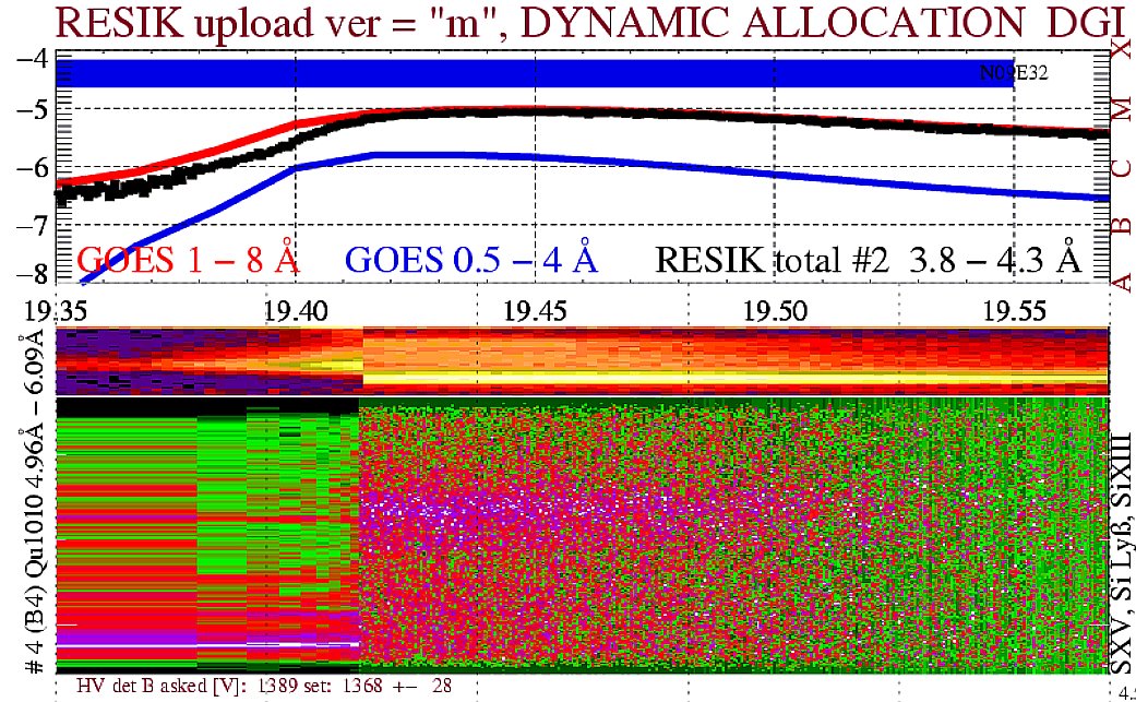
An example of the switch between the ORD1/ORD3 mode is presented in the figure
below. The switching took place around 19:24:50 UT, when the GOES level was
about C8.
Report prepared by: Barbara Sylwester bs@cbk.pan.wroc.pl
& Janusz Sylwester js@cbk.pan.wroc.pl
ORD3 mode design & programming: Mirek
Kowalinski, mk@cbk.pan.wroc.pl
Selection of ADS settings: Marek
Siarkowski, ms@cbk.pan.wroc.pl
The report presented has been done in "real time" and so it may
contain jargon, blunders, or trivialities. We do not have also an English native
speaker in our Wroclaw group! We would be happy to discuss problems mentioned
above in more details if necessary.
RESIK data are in the open public domain and can be requested from: http://surfwww.mssl.ucl.ac.uk/surf/data_request.html.
Previous RESIK_weekly notes are in the
archive:
http://www.cbk.pan.wroc.pl/resik_archive.htm
Page made on 12 December 2002 by: Jarek Bakala jb@cbk.pan.wroc.pl