(Week 52, 2002, 23 Dec. - 29 Dec.)
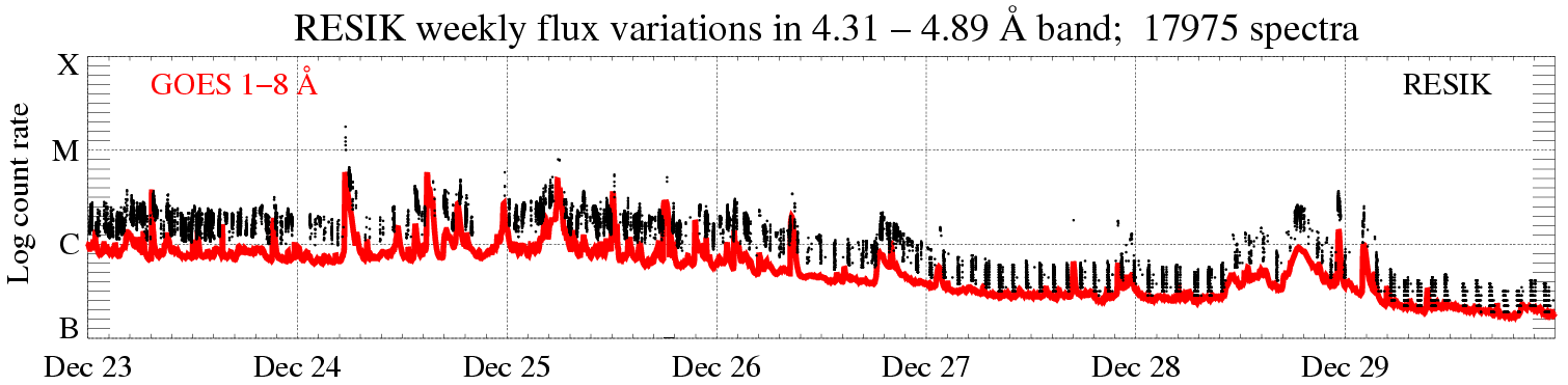
In the display above (click to enlarge), the solar X-ray fluence seen by RESIK (black points) is plotted atop GOES red line. Only periods with good spectral measurements are indicated. The total number of good spectral measurements is given in the title line.
Operation mode: |
'3rd order reflections' (ORD3) is used as
stand-by mode. 3rd order spectra observations are indicated on the main catalogue page http://www.cbk.pan.wroc.pl/2002.htm (cf. green boxes).
|
|
|
Starting on Mon, Dec. 23 15:08:24, a modified ORD1
standard has been introduced |
||
Calibrations made: |
No calibrations made |
|
ADS Settings: |
|
|
|
|
||
| (ORD1) HV: Det. A - 1450 V, Det. B - 1419 V. | (ORD3) HV: Det. A - 1389 V, Det. B - 1328 V. | ||||||
|
Channel |
l Band |
ADS |
Channel |
l Band |
ADS |
||
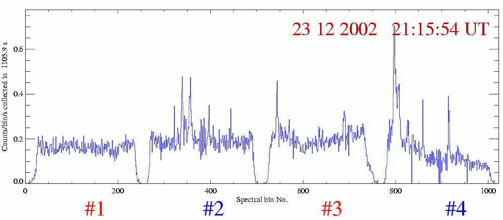
| #1 | #2 | 3.37 - 3.88 Å | 35 - 85 | #1 | #2 | 1.16 - 1.29 Å | 110 - 230 |
| #2 | #0 | 3.82 - 4.33 Å | 80 - 160 | #2 | #0 | 1.27 - 1.44 Å | 110 - 230 |
| #3 | #3 | 4.31 - 4.89 Å | 55 - 110 | #3 | #3 | 1.44 - 1.63 Å | 110 - 230 |
| #4 | #1 | 4.96 - 6.09 Å | 135 - 200 | #4 | #1 | 1.65 - 2.03 Å | 140 - 230 |
|
software indexes |
|
software indexes |
|||||
|
spectroscopic notation (papers) |
spectroscopic notation (papers) |
||||||
Data gaps due to missing telemetry: ~ 2 h.
Two HV power supply units (PSU) within RESIK are of basic importance for the instrument operation, as they provide stabilized voltage difference between detectors corpus and anode. Since detectors operate in the proportional regime, the important aspect of these HV-PSU is the accuracy of the voltage settings and its short- and long-term stability. In Fig. 1, we show the placement of HV-PSU within RESIK spectrometers A and B.
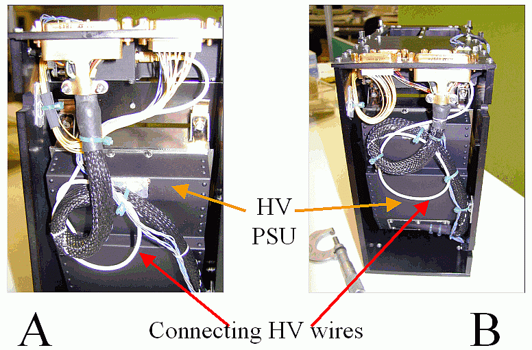
Figure 1. Photographs of the RESIK spectrometers A & B showing the high voltage power supply units. The white thicker wires (red arrows) connect the unit with the detectors anodes.
The HV-PSU units have been manufactured at Rutherford-Appleton Laboratory, UK under supervision of dr. Jim Lang.
The units are designed according to the same specifications as the BCS Yohkoh (http://ydac.mssl.ucl.ac.uk/guides/index.html).
Each HV-PSU can provide eight levels of HV, stabilized to within ± 1V. The selection of working voltage can be made individually by the command from the on-board computer COMP, for each of the
detectors.
In the Table, we provide nominal voltages for each of the stetting levels.
| HV Level
address |
Detector A
[V] |
Detector B
[V] |
| 0 | 1328 | 1328 |
| 1 | 1358 | 1358 |
| 2 | 1389 | 1389 |
| 3 | 1419 | 1419 |
| 4 | 1450 | 1450 |
| 5 | 1480 | 1480 |
| 6 | 1511 | 1511 |
| 7 | 1541 | 1541 |
Values in red represent the settings used during the detector callibration, and the initial standard values used in first order spectral measurments are given in green. Grey and blue boxes indicate present values used in ORD1 and ORD3 observing modes respectively. Values of anode voltages are controlled in flight (each DGI) and are found to be in agreement (to within 5 V measurement accuracy) with the nominal values.
Report prepared by: Janusz Sylwester js@cbk.pan.wroc.pl
and Mirek Kowalinski mk@cbk.pan.wroc.pl
The report presented has been done in "real time" and so it may
contain jargon, blunders, or trivialities. We do not have also an English native
speaker in our Wroclaw group! We would be happy to discuss problems mentioned
above in more details if necessary.
RESIK data are in the open public domain and can be requested from: http://surfwww.mssl.ucl.ac.uk/surf/data_request.html.
Previous RESIK_weekly notes are in the
archive: http://www.cbk.pan.wroc.pl/resik_archive.htm
Page made on 31 December 2002 by: Jarek Bakala jb@cbk.pan.wroc.pl