![]()
RESIK & Diogeness NEWS
|
|
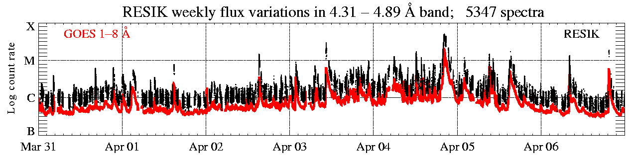
(Week 14, 2003, 31 Mar. - 6 Apr.)
In the display above (click to enlarge), the solar X-ray fluence seen by RESIK (black points) is plotted atop GOES red line. Only periods with good spectral measurements are indicated. The total number of good spectral measurements is given in the title line.
|
Operation mode: |
2 s DGI has been used, except for the
interval between '3rd order
reflections' (ORD3) is used as stand-by mode.
|
|
|
Calibrations made: |
No calibrations made
| |
|
ADS Settings: |
Since Apr. 05, 00:47:05 UT, new values are used (see
Table below). | |
|
| ||
| (ORD1) HV: Det. A - 1450 V, Det. B - 1419 V. | (ORD3) HV: Det. A - 1389 V, Det. B - 1328 V. | ||||||
|
Channel |
l Band |
ADS |
Channel |
l Band |
ADS | ||
| #1 | #2 | 3.37 - 3.88 Å | 45 - 120 | #1 | #2 | 1.16 - 1.29 Å | 110 - 230 |
| #2 | #0 | 3.82 - 4.33 Å | 75 - 170 | #2 | #0 | 1.27 - 1.44 Å | 110 - 230 |
| #3 | #3 | 4.31 - 4.89 Å | 105 - 170 | #3 | #3 | 1.44 - 1.63 Å | 110 - 230 |
| #4 | #1 | 4.96 - 6.09 Å | 145 - 205 | #4 | #1 | 1.65 - 2.03 Å | 140 - 230 |
|
|
| ||||||
Data gaps due to missing telemetry: ~ 10 h.
Note, that the link to the catalogue page is now: http://www.cbk.pan.wroc.pl/resik_catalogue.htm.
RESIK Effective Areas First Order Reflection
For quantitative analysis of the observed spectra it is of basic importance to know the response function of the spectrometer. This response function is conveniently represented as so-called effective area S, expressed in [cm2].
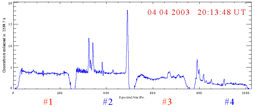
Known effective areas allow to convert the rates [cts/s/bin] observed in each RESIK spectral bin into absolute fluxes [photons/cm2/s]. Determination of wavelength (energy) dependence of effective area is a primary objective of the instrument ground and in-flight calibration and involves detailed knowledge of the instrument construction details.
We
present below
version_1.0 of
effective area dependence on the wavelength
S(λ)
calculated according to the following formula (based on Jim Langs RAL notice,
1995):
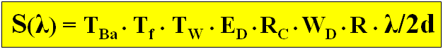
| TBa | - | transmission of the detector strengthening bars (probability) |
| Tf (λ) | - | transmission of the thermal filter (probability) |
| Tw(λ) | - | transmission of the detector window (probability) |
| ED (λ) | - | probability of absorption in the detector gas |
| RC (λ) | - | total reflection coefficient from the monocrystal [radians] |
| WD | - | width of the detector [cm] |
| R | - | bent radius of (convex) crystal [cm] |
| 2d | - | crystal constant (doubled spacing) [Å] |
| λ | - | wavelength [Å] |
![]()
Similar quantities for detectors beryllium window:
![]()
Probability of absorption in the detector gas mixture of Ar, Xe and CO2, dd - is the detector depth for absorption:
![]()
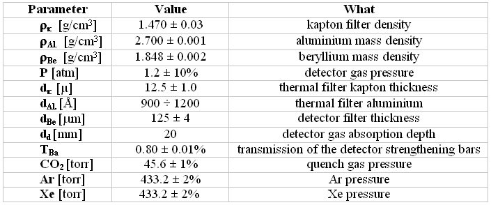
In the
calculations, we have used κ(λ) from Tabulations from webpage
http://www-cxro.lbl.gov/optical_constants/. The values of other parameters used are given in
the Table.
Values of the total reflection coefficient RC have been taken from interpolation of theoretical ideal, single crystal calculations performed using Cowan & Brennan Code (Brennan S. and Cowan P.L.: 1992, Rev. Sci. Instr., 63, 850). Uncertainties have been estimated based on comparison with respective data for double crystal reflectivities from Figures 26 and 27 given by Anthony Burek (Space Sci. Instrumentation, 2, 53 104, 1976)
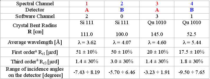
Table 1. Values of parameters used in calculations of RESIK effective areas.
In the plot below we present calculated dependence of S(λ) for all channels. It should be noted that the values calculated represent the FIRST ORDER approach only as we have made a number of assumptions, which will be relaxed one by one as further progress in laboratory calibration is reached. The assumptions to be relaxed are:
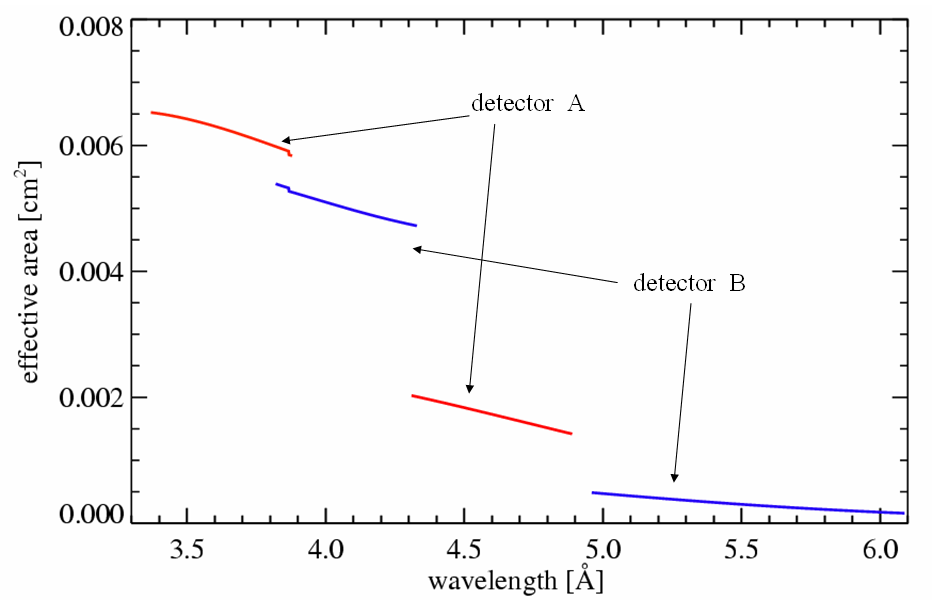
Figure 1. Wavelength dependence of the RESIK effective area for the first order reflection.
The report presented has been done in "real time" and so it may contain jargon, blunders, or trivialities. We do not have also an English native speaker in our Wroclaw group! We would be happy to discuss problems mentioned above in more details if necessary.
RESIK data are in the open public domain and
can be requested from: http://surfwww.mssl.ucl.ac.uk/surf/data_request.html.
Previous RESIK_weekly notes are in the archive: http://www.cbk.pan.wroc.pl/resik_archive.htm
Page made on 11 April 2003 by: Anna Kepa ak@cbk.pan.wroc.pl and Jarek Bakala jb@cbk.pan.wroc.pl