![]()
RESIK & Diogeness NEWS
|
|
(Week 17, 2003, 21 Apr. - 27 Apr.)
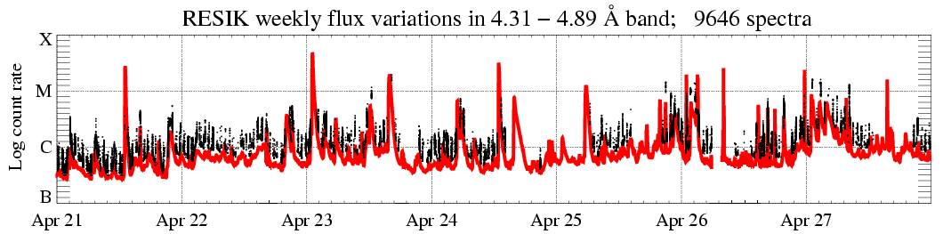
In the display above (click to enlarge), the solar X-ray fluence seen by RESIK (black points) is plotted atop GOES red line. Only periods with good spectral measurements are indicated. The total number of good spectral measurements is given in the title line.
|
Operation mode: |
1 s DGI has been used '3rd order
reflections' (ORD3) is used as stand-by mode.
|
|
|
Calibrations made: |
No calibrations made
| |
|
ADS Settings: |
| |
|
| ||
| (ORD1) HV: Det. A - 1480 V, Det. B - 1419 V. | (ORD3) HV: Det. A - 1389 V, Det. B - 1328 V. | ||||||
|
Channel |
l Band |
ADS |
Channel |
l Band |
ADS | ||
| #1 | #2 | 3.37 - 3.88 Å | 115 - 195 | #1 | #2 | 1.16 - 1.29 Å | 110 - 230 |
| #2 | #0 | 3.82 - 4.33 Å | 75 - 170 | #2 | #0 | 1.27 - 1.44 Å | 110 - 230 |
| #3 | #3 | 4.31 - 4.89 Å | 170 - 250 | #3 | #3 | 1.44 - 1.63 Å | 110 - 230 |
| #4 | #1 | 4.96 - 6.09 Å | 145 - 205 | #4 | #1 | 1.65 - 2.03 Å | 140 - 230 |
|
|
| ||||||
Data gaps due to missing telemetry: ~ 33 h.
Note, that the link to the catalogue page is now: http://www.cbk.pan.wroc.pl/resik_catalogue.htm.
RESIK Dispersion Simple Approach
Please note update of the
weekly 15, 2003 RESIK and RHESSI Observations of the Thermal Component
of Flare X-ray Emission - the plot just has been added showing RHESSI and RESIK energy spectra
plotted together.
For purposes of
line identification it is of primary interest to know the relation between the
wavelength of the crystal-diffracted radiation and the spectral bin No. where it
is recorded. RESIK spectrometer blocks have been pre-calibrated in this respect
at Rutherford Appleton Laboratory (RAL) in mid 2000 and the so-called linearity
tests of the detectors have been made at Mullard Space Science Laboratory (MSSL).
The results of the calibrations are stored on files and await for the
interpretation. The interpretation appears to be a large task, for which we do
not have at present enough human resources in Wroclaw.
However, the knowledge of dispersion is a necessity, so we have made an attempt
to estimate it based on the observed positions of identified emission lines and
their respective wavelengths known from theory or earlier measurements.
In Figure 1, we present a portion of the construction scheme showing the crystal-detector
geometry.
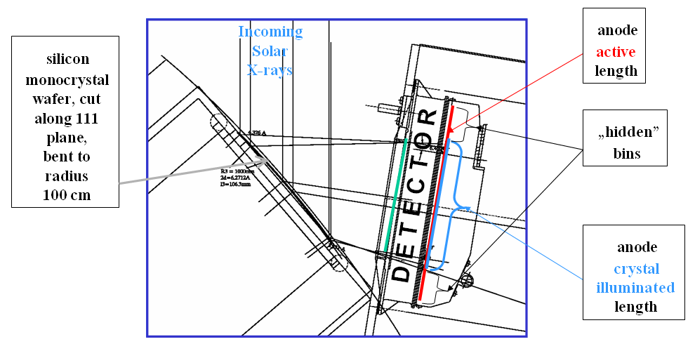
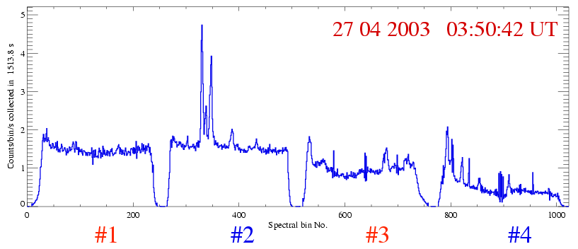
Figure 1. Section of the construction scheme (dr. Charlie Brown, NRL) showing relative orientation of the bent crystal wafer, the detector Be window aperture, the anode, hidden bins and crystal-illuminated portions of the anode for RESIK channel #2.
It is seen from
the scheme, that the crystal-diffracted (or reflected) X-rays illuminate the
position-sensitive detector through the Be entrance window over the length of ~9
cm (green bar). Solar X-ray spectrum is formed over the length of a
blue portion of the anode only;
hidden bins are not directly illuminated from the Sun. Owing to the special
construction, the position of X-ray photon absorbed in the Ar-Xe detector gas
can be determined from the ratio of charge measured on both ends of detectors
wedge-and-wedge position encoding system. The accuracy of photon arrival
position determination is ~ 0.3 mm, therefore ~ 500 position bins can be
resolved over the length of the anode.
In order to secure the maximum possible resolution of the 8-bit position readout system, a
special so-called position lookup table is used, stored in the spectrometers
EPROM memory. The lookup table is arranged so to decrease the accuracy of
position readout in the hidden bin portions, increasing in return, the accuracy
of the readout in the portion of anode sensitive to crystal-reflected radiation.
The characteristic of the adopted position encoding (or bin compression) scheme is shown in Figure 2.
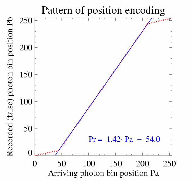
Figure 2. Electronic bin compression pattern stored in the spectrometer memory lookup table. The 45 (hidden) end position bins are compressed to 10 bins (with indexes: 0 9 and 246 255). Saved (70) bins increase resolution in the central portion of the detector where the spectrum is recorded, pushing the spectral bin size down towards the intrinsic detectors position resolution.
The adopted compression scheme stretches the spectral dispersion by a factor of 1.42 in the
central portion of the detector. This effect will be taken into account in the
forthcoming analysis of the ground calibration data.
For purposes of the present prompt analysis of RESIK spectra, we decided to use a simple linear
approximation for the spectral dispersion. Derived parameters (see Table 1)
describing the wavelength bin No. dependence have been determined for a
specific flare observed early in the mission on 22 April 2002 at 00:10 UT. For
this flare (M4.4, S06W12), the dependence of wavelength λ [Å] and the
(electronic) bin No pb for the first order reflection is:
λ =b0i + d0ipb
Where d0i represents (assumed linear) dispersion in [Å]/bin in a particular spectral
channel i. b0i represents the shortwavelength limit in each channel.
Values of coefficients have been determined (by JS and KJHP Ken Phillips )
from (pairs of) the observed positions of stronger identified emission lines and
their known theoretical wavelengths. Estimated dispersion values are roughly
inversely proportional to the bent radii of the crystals (as expected).
Depending on the position of the source (flare), the lines move along the
dispersion of the spectrometer. The calibration of this effect is in progress.
|
Channel |
Software |
b0i |
d0i |
1 |
2 |
3.3150 |
0.00248 |
2 |
0 |
3.7705 |
0.00247 |
3 |
3 |
4.2503 |
0.00297 |
4 |
1 |
4.9202 |
0.00547 |
Prepared by: Janusz Sylwester js@cbk.pan.wroc.pl and Barbara Sylwester bs@cbk.pan.wroc.pl
The report presented has been done in "real time" and so it may contain jargon, blunders, or trivialities. We do not have also an English native speaker in our Wroclaw group!
We would be happy to discuss problems mentioned above in more details if necessary.
RESIK data are in the open public domain and can be requested from: http://surfwww.mssl.ucl.ac.uk/surf/data_request.html.
Previous RESIK_weekly notes are in the archive: http://www.cbk.pan.wroc.pl/resik_archive.htm
Page made on 2 May 2003 by: Anna Kepa ak@cbk.pan.wroc.pl and Jarek Bakala jb@cbk.pan.wroc.pl